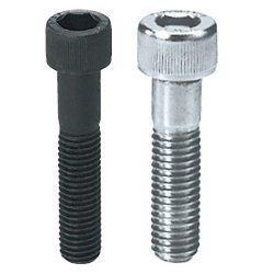
Extra Low Profile Head Hex Socket Head Cap Screw -Single Item / Sales by Carton / Loosening Prevention Treated -Sales by Package-【1-500 Pieces Per Package】 (PACK-CBSTS6-8-YBM)
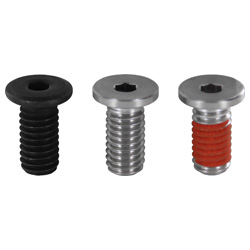
- Promotional pricing ends 30/11/2024
- Volume Discount
Product Details:
Manufacturer part number: PACK-CBSTS6-8-YBM
Brand: MISUMI
Price: 21.91 €
Delivery time: 5 Days
Technical Data:
[M] Diameter (Screw Thread) Nominal: 6
[L] Length: 8 mm
Material: [Stainless Steel] EN 1.4567 Equiv.
Surface Treatment: Threadlocker Adhesive Applied
[P] Pitch: 1 mm
- Order quantities extended (D-JIT)
- Stock
(i)Remark
- Please check the content on our website as the PDF does not contain the most up-to-date information.
Part Number
Once your search is narrowed to one product,
the corresponding part number is displayed here.
PACK-CBSTS6-8-YBM
- Drawing / Specifications
- 3D Preview 3D preview is available after complete configuration
- Part Numbers
- More Information
- Catalog
Back to the Category Flat Head Screws/Low Head Screws
No Thread Locking Compound (Available in Single item / Box (150 pcs. or more))

With Thread Locking Compound, Package Sale (10 pcs.), EN 1.4567 Equiv. only

| M | L | (a) | (b) |
| M3 | 4 to 10 | Fully Threaded Section | 0 |
| 12 | 3 | 2 | |
| M4 | 5 to 10 | Fully Threaded Section | 0 |
| 12 to 16 | 4 | 2 | |
| M5 | 6 to 10 | Fully Threaded Section | 0 |
| 12 to 20 | 5 | 2 | |
| M6 | 8 to 10 | Fully Threaded Section | 0 |
| 12 to 25 | 6 | 2 |
Available dimensions and tolerances can be found under the tab More Information.
No Thread Locking Compound (Available in Single item / Box (150 pcs. or more))
Type | [M] Material | [H] Hardness | [S] Surface Treatment | Strength Class * | Head Strength Class |
| CBSS | EN 1.7220 Equiv. | 32 to 39HRC | Black Oxide (Black) | 10.9 | 5.8 (M10 4.8) |
| CBSA | Trivalent Chromate (Silver) | ||||
| CBSR | LTBC Plating | ||||
| CBSM | Bright Chrome Plating | ||||
| CBSTS | EN 1.4567 Equiv. | — | — | (Note 1) | — |
| BOX−CBSTS |
| Thread | Tightening Torque (Reference Value) | ||
| N⋅m | |||
| CBSS CBSA | CBSR | CBSTS BOX−CBSTS PACK-CBSTS | |
| M2 | 0.12 | - | 0.25 |
| M2.5 | 0.24 | - | 0.42 |
| M3 | 0.6 | 0.9 | 0.8 |
| M4 | 1.2 | 2.2 | 1.6 |
| M5 | 2.1 | 3.3 | 3.0 |
| M6 | 3.0 | 5.9 | 5.0 |
| M8 | 6.0 | 10.3 | 8.6 |
| M10 | 10.8 | - | 15.4 |
With Thread Locking Compound, Package Sale (10 pcs.), EN 1.4567 Equiv. only
·Single item with thread locker applied is not available.
· (a) It is applied to the entire circumference.
·Cannot be used repeatedly.
The locking agent is encased in a micro capsule, once the screw is tightened, it breaks and the agent will come out.
Although it is possible that not every capsule has been cracked, the thread locking effect may be less after the second time.
Please be aware that contact with oil will reduce performance.
| TYPE | Treatment Code | [M] Material | Treatment |
| PACK-CBSTS | YBM | EN 1.4567 Equiv. | Thread Locking Compound (Epoxy Resin Adhesive) |
Further specifications can be found under the tab More Information.
| Part Number |
| CBSA6−12 |
| Part Number | — | Treatment Code |
| PACK− CBSTS 3− 5 | — | YBM |
Flathead Screw Selection Details
- Drive: hex (external hex), hexagon socket, hex socket (Torx)
- Strength classes: 8.8, 10.9, A2-50, A4-80
- Threads: M2, M2.5, M2.6, M3, M4, M5, M6, M8, M10, M12
- Thread lengths: 3 mm – 50 mm
- Surface coating: burnished, nickel-plated, chrome-plated, LTBC coating
- Materials: stainless steel, steel
Description/Basics
The screwed connection is one of the most commonly used methods among the soluble compounds. Due to their flat head, flathead screws have various advantages over conventional screws.
Screws with a flat head are often utilised in places that need to form a flat level as much as possible.
Due to their head geometry, flathead screws allow counterbores to be made less deep or completely omitted. This allows covers to be made thinner walls and thus save weight. These advantages also result in cost savings through material savings and the elimination or shortening of production steps. The MISUMI flat-head screws are thus ideal for mounting sheet metal, thin panels, housing covers and other covers.
As opposed to the head form of commercially available screws, the flathead screw reduces the risk of injury at accessible locations, such as housing covers, mounting flaps, etc. This also eliminates the frequently required plastic caps on large screw heads.
Contrary to the standard flathead screws (DIN 921, DIN 922 and DIN 923), MISUMI has flathead screws with hexagon socket, hexagon socket (Torx) and external hexagon. These drive types reduce slipping during assembly compared to typical cross or slotted drives.
MISUMI offers flathead screws in various strength classes.
However, due to the delicate head of flathead screws, the strength on the head can be lower than that on the thread, since there is less material available. The respective strength class is therefore assigned to the individual flathead screws (see Basic Properties).
Areas of Application
Flathead screws are intended for fastening of joining parts. Often, the flathead screws are used for housing covers or in applications requiring low weight.
Thanks to the multi-selectable surface treatments, flathead screws are particularly resistant to environmental influences. This allows flathead screws to be used in almost all industry sectors of plant engineering and mechanical engineering.
The benefits of using flathead screws are versatile. The main advantages of flathead screws are their low weight and space savings.
To utilise a flathead screw with vent function, e.g., for pressure equalization, MISUMI also offers hollow screws with a flat head.
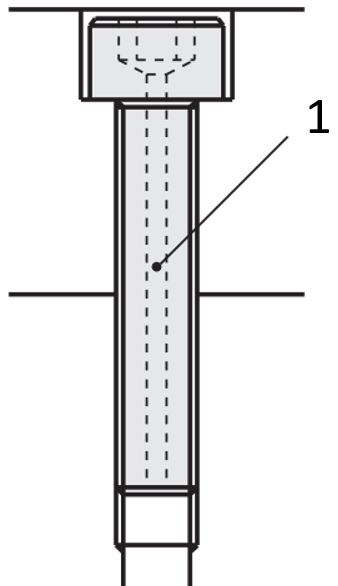
(1) Through-hole for exhaust air
Materials
Strength classes
The strength class gives the tensile strength [R m ] and yield strength [R e ], or expansion limit [R p-0.2] of the screw.
Screws that are subject to a strength class are often marked by the strength class on the screw head. For some screws, the reference to the strength class is missing. In such cases, please refer to the Screw Data Sheet (see Basic Properties).
The screw strength class is an indication of the tensile strength and the expansion limit of a screw. The higher the specification of the strength class, the higher the tensile strength and expansion limit. In principle, a distinction is made between steel and stainless steel (stainless steel).
Stainless steel screws are marked with the letters A, C and F (e.g., A2-50). Steel screws are marked with two numbers, separated by a dot (e.g., 8.8).
The tensile strength and elongation limit can be determined based on this information. Which of the two values and safety number are used for the further calculation of the screws depends on the applied load case.
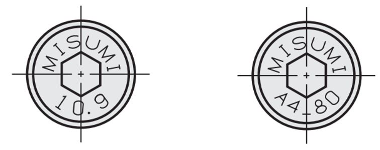
Example of a strength marking
Tensile strength steel
Example: 8.8
R m = 8 x 100 N/mm 2 = 800 N/mm 2
The expansion limit of the screw material is the resistance value that can be applied to the material without permanent deformation. Thus, the screw can return to its original length after this stress (elastic range).
If the elastic range is exceeded, there is a permanent (plastic) deformation, which can end in a tear/fracture of the material upon further stress.
To determine the value, both values of the strength specification are multiplied with each other and additionally by a factor of 10.
Example 8.8
R p-0.2 = 8 x 8 x 10 N/mm 2 = 640N /mm 2
Tensile strength stainless steel
For stainless steel screws, the strength specification begins with the specification of the material group used.
The most common stainless steel screw is the A2 stainless steel screw, which is manufactured from (colloquially speaking) V2A material. In this example, the A2 screw is made of austenitic stainless steel.
Ferritic stainless steel screws are often marked with a [F] at the beginning and martensitic stainless steel types with a [C].
Unlike the steel screws, the second value of the strength specification is multiplied by a factor of 10 for the stainless steel screws in order to determine the tensile strength of the screw material. The expansion limit [R p-0.2] must be determined in tabular form based on the expansion limit of the raw material or the manufacturer.
Example A2-50
R m = 50 x 10 N/mm 2 = 500 N/mm 2
Screws without specification of this strength classification have manufacturer-bound values that must be taken from the respective data sheets or manufacturer information. This often occurs with screws with special shape and treatment.
Coatings
MISUMI’s flathead screws are available in burnished, chrome-plated, or nickel-plated to best protect them from corrosion.
As an alternative to one of these surface treatments, flathead screws can also be coated with LTBC. The LTBC coating (Low Temperature Black Chrome Platinum) is a surface coating that protects against corrosion and has low reflection. The coating consists of a 5 μm thick chrome ceramic layer with fluoropolymer infusion and forms a black film. In addition, the LTBC coating is resistant to cracking and bending and it is thus resistant to peeling due to extreme or repeated bending. This makes LTBC-coated flathead screws particularly suitable for areas where corrosion or light reflections are undesirable.
Dimensions
Compared to an M5 standard cylinder head screw with 5 mm head height, with a flathead screw it is possible to save up to 4 mm of head height.
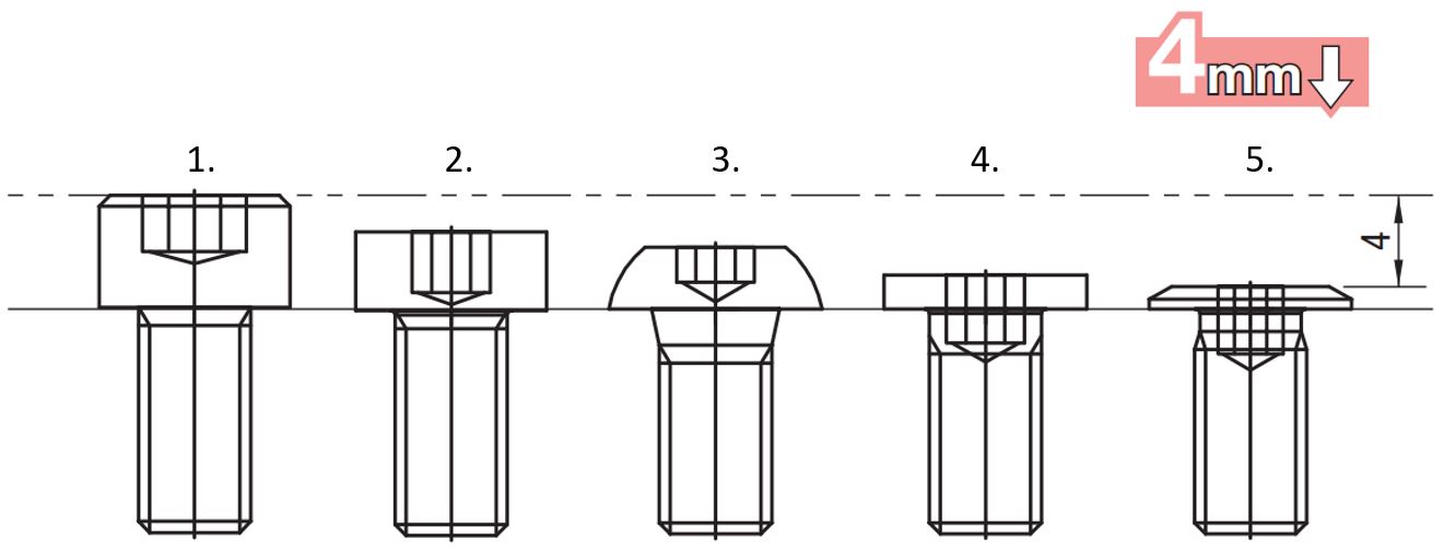
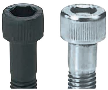
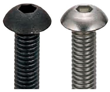
(1) Standard cylinder head screws, (2) Flat head, (3) Safety screws, (4) Very flat head, (5) Ultra flat head
| Products | Hexagon socket screws | flat head | Safety screws | very flat head | ultra flat head | |
 |  |  | 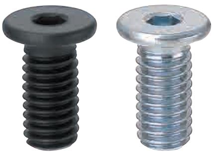 | 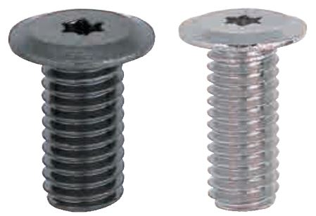 | ||
| P. 172, 174, 175 | P. 194 | P. 185 | P. 195 | P. 196 | ||
| Head height (in mm) | ||||||
| M | 2 | 2 | 1.3 | 1.3 | 1.1 (min.*) | 0.5 |
| 2.5 | 2.5 | 1.6 | 1.5 | 1.3 (min.*) | 0.6 | |
| 3 | 3 | 2 | 1.65 | 1.5 | 0.8 | |
| 4 | 4 | 2.8 | 2.2 | 1.5 | 0.9 | |
| 5 | 5 | 3.5 | 2.75 | 1.5 | 1 | |
| 6 | 6 | 4 | 3.3 | 1.5 | 1.2 | |
| 8 | 8 | 5 | 4.4 | 1.5 | - | |
| 10 | 10 | 6 | 5.5 | 1.5 | - | |
| 12 | 12 | 7 | - | - | - | |
Bolt Head Height Comparison Chart
*Head height varies by material.
Tightening torques/torques
| Products | flat head | very flat head | ultra flat head | |||||
| Steel | Steel, stainless steel | Stainless steel | Steel | Stainless steel | Steel | Steel | ||
| Strength class | 10.9 | 8.8, A4-80 | A2-50 | 5.8 (M10, 4.8) | - | - | - | |
| Tensile strength (N/mm 2) | 1040 | 800 | 500 | 500 (M10, 400) | 400 | 350 (M2, 200) | 350 (M2, 200) | |
| M | 2 | - | - | 0.25 | 0.25 | 0.25 | 0.16 | 0.178 |
| 2.5 | - | - | 0.42 | 0.82 | 0.42 | 0.35 | - | |
| 3 | 1.1 | 0.9 | 0.8 | 0.9 | 0.8 | 0.6 | 0.63 | |
| 4 | 4.0 | 1.8 | 1.6 | 1.8 | 1.6 | 1.1 | 1.5 | |
| 5 | 6.1 | 3.6 | 3.2 | 3.2 | 3.0 | 2.2 | 3.0 | |
| 6 | 10.5 | 7.2 | 6.5 | 5.2 | 5.0 | 5.0 | 5.2 | |
| 8 | 18.4 | 10.8 | 9.7 | 9.0 | 8.6 | - | - | |
| 10 | - | 31.5 | 28.4 | 16.2 | 15.4 | - | - | |
| 12 | - | 45.0 | 40.5 | - | - | - | - | |
Note: The above values are for comparison purposes only (reference values).
Further specifications can be found under the tab More Information.
Installation Information
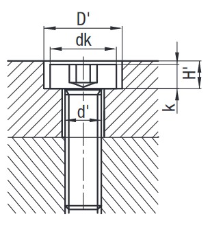
Dimensions of the screw and counterbores
| Thread (d) | flat head | very flat head (stainless steel screw) | ultra flat head Hexagon socket | ultra flat head Torx | ||||||||||||||||
| d' | dk | D' | k | H' | d' | dk | D' | k | H' | d' | dk | D' | k | H' | d' | dk | D' | k | H' | |
| M2 | 2.5 | 3.8 | 5 | 1.3 | 1.5 | 4 | 4 | 5 | 1.1 (1.5) | 1.3 (1.7) | 2.5 | 4 | 5 | 0.5 | 0.7 | 2.5 | 4 | 5 | 0.5 | 0.7 |
| M2.5 | 3 | 4.5 | 5.5 | 1.6 | 1.8 | 3 | 5 | 6 | 1.3 (1.5) | 1.5 (1.7) | 3 | 5 | 6 | 0.6 | 0.8 | - | - | - | - | - |
| M3 | 3.5 | 5.5 | 6.5 | 2 | 2.3 | 3.5 | 6 | 7 | 1.3 (1.5) | 1.6 (1.8) | 3.5 | 6 | 7 | 0.8 | 1.1 | 3.5 | 7 | 8 | 0.8 | 1.1 |
| M4 | 4.5 | 7 | 8 | 2.8 | 3.2 | 4.5 | 8 | 9 | 1.5 | 1.9 | 3.4 | 8 | 9 | 1.1 | 1.3 | 4.5 | 8 | 9 | 0.9 | 1.3 |
| M5 | 5.5 | 8.5 | 9.5 | 3.5 | 3.9 | 5.5 | 9 | 10 | 1.5 | 1.9 | 5.5 | 9 | 10 | 1.4 | 1.4 | 5.5 | 9 | 10 | 1 | 1.4 |
| M6 | 6.5 | 10 | 11 | 4 | 4.5 | 6.5 | 10 | 11 | 1.5 | 2 | 6.5 | 10 | 11 | 1.7 | 1.7 | 6.5 | 12 | 13 | 1.2 | 1.7 |
| M8 | 9 | 13 | 14 | 5 | 5.6 | 9 | 13 | 14 | 1.5 | 2.1 | - | - | - | - | - | - | - | - | - | - |
| M10 | 11 | 16 | 17.5 | 6 | 6.8 | 11 | 16 (15) | 17.5 (16.5) | 1.5 | 2.3 | - | - | - | - | - | - | - | - | - | - |
| M12 | 14 | 18 | 20 | 7 | 8 | - | - | - | - | - | - | - | - | - | - | - | - | - | - | - |
Further specifications can be found under the tab More Information.




Part Number:
- In order to open the 3D preview, the part number must be fixed.
3D preview is not available, because the part number has not yet been determined.
Part Number
|
|---|
| PACK-CBSTS6-8-YBM |
| Part Number |
Standard Unit Price
| Number of pc(s). included in pkg. | Minimum order quantity | Volume Discount | RoHS | [M] Diameter (Screw Thread) Nominal | [L] Length (mm) | Material | Surface Treatment | [P] Pitch (mm) | Additional Shape | Strength Class (Steel) | Sales Unit | Application | Material Certificate | Material Certificate: Material | Material Certificate: Material (Note) | Screw M Diameter | Size (X Notation) (mm) | Size (- Notation) (mm) | Standard Name (Material) | |
|---|---|---|---|---|---|---|---|---|---|---|---|---|---|---|---|---|---|---|---|---|---|---|
21.91 € | 10 Pieces Per Package | 1 pack | Available | 5 Days | - | 6 | 8 | [Stainless Steel] EN 1.4567 Equiv. | Threadlocker Adhesive Applied | 1 | Threadlocker Adhesive Applied | - | Box, Pkg. | Standard | Available | SUSXM7 | Screw Tip: Epoxy Resin Adhesive | M6 | M6×8 | M6-8 | Stainless Steel |
Loading...
Back to the Category Flat Head Screws/Low Head Screws
| Type | M × P | A | B | t max. | (e) max. | r | T |
| CBSS | 2 × 0.4 | 4 | 1.3 | 1.2 | 1.2 | 0.1 or More | 1.1 |
| 2.5 × 0.45 | 5 | 1.3 | 1.5 | 1.5 | 1.3 | ||
| 3 × 0.5 | 6 | 1.5 | 2 | 1.6 | |||
| 4 × 0.7 | 8 | 2 | 2.5 | 1.6 | 0.2 or More | 1.5 | |
| 5 × 0.8 | 9 | 3 | 3 | 2 | |||
| 6 × 1.0 | 10 | 3 | 4 | 2.5 | 0.25 or More | ||
| 8 × 1.25 | 13 | 4 | 5 | 3 | 0.4 or more | ||
| 10 × 1.5 | 16 | 5 | 6 | 3.5 | |||
| CBSA | 2 × 0.4 | 4 | 1.3 | 1.2 | 1.2 | 0.1 or More | 1.1 |
| 2.5 × 0.45 | 5 | 1.3 | 1.5 | 1.5 | 1.3 | ||
| 3 × 0.5 | 6 | 1.5 | 2 | 1.6 | |||
| 4 × 0.7 | 8 | 2 | 2.5 | 1.6 | 0.2 or More | 1.5 | |
| 5 × 0.8 | 9 | 3 | 3 | 2 | |||
| 6 × 1.0 | 10 | 3 | 4 | 2.5 | 0.25 or More | ||
| 8 × 1.25 | 13 | 4 | 5 | 3 | 0.4 or more | ||
| 10 × 1.5 | 16 | 5 | 6 | 3.5 | |||
| CBSR | 3 × 0.5 | 6 | 1.5 | 2 | 1.6 | 0.1 or More | 1.3 |
| 4 × 0.7 | 8 | 2 | 2.5 | 1.6 | 0.2 or More | 1.5 | |
| 5 × 0.8 | 9 | 3 | 3 | 2 | |||
| 6 × 1.0 | 10 | 3 | 4 | 2.5 | 0.25 or More | ||
| 8 × 1.25 | 13 | 4 | 5 | 3 | 0.4 or more |
| Type | M × P | A | B | t max. | (e) max. | r | T |
| CBSTS | 2 × 0.4 | 4 | 1.3 | 1.2 | 1.2 | 0.2 or More | 1.1 |
| 2.5 × 0.45 | 5 | 1.3 | 1.5 | 1.5 | 1.3 | ||
| 3 × 0.5 | 6 | 1.5 | 2 | 1.6 | 1.5 | ||
| 4 × 0.7 | 8 | 2 | 2.5 | 1.6 | |||
| 5 × 0.8 | 9 | 3 | 3 | 2 | |||
| 6 × 1.0 | 10 | 3 | 4 | 2.5 | |||
| 8 × 1.25 | 13 | 4 | 5 | 3 | |||
| 10 × 1.5 | 15 | 5 | 6 | 3.5 | |||
| BOX-CBSTS | 2 × 0.4 | 4 | 1.3 | 1.2 | 1.2 | 0.2 or More | 1.5 |
| 2.5 × 0.45 | 5 | 1.3 | 1.5 | 1.5 | |||
| 3 × 0.5 | 6 | 1.5 | 2 | 1.6 | 1.3 | ||
| 4 × 0.7 | 8 | 2 | 2.5 | 1.6 | 1.5 | ||
| 5 × 0.8 | 9 | 3 | 3 | 2 | |||
| 6 × 1.0 | 10 | 3 | 4 | 2.5 | |||
| 8 × 1.25 | 13 | 4 | 5 | 3 | |||
| 10 × 1.5 | 15 | 5 | 6 | 3.5 | |||
| PACK-CBSTS | 2 × 0.4 | 4 | 1.3 | 1.2 | 1.2 | 0.2 or More | 1.5 |
| 2.5 × 0.45 | 5 | 1.3 | 1.5 | 1.5 | |||
| 3 × 0.5 | 6 | 1.5 | 2 | 1.6 | |||
| 4 × 0.7 | 8 | 2 | 2.5 | 1.6 | |||
| 5 × 0.8 | 9 | 3 | 3 | 2 | |||
| 6 × 1.0 | 10 | 3 | 4 | 2.5 | |||
| 8 × 1.25 | 13 | 4 | 5 | 3 | |||
| 10 × 1.5 | 15 | 5 | 6 | 3.5 |
| Thread | A Dimension Tolerance | ||
| CBSS CBSA | CBSR | CBSTS BOX−CBSTS PACK-CBSTS | |
| M2 | +0.18 to -0.3 | - | +0 to -0.3 |
| M2.5 | - | ||
| M3 | +0 to -0.3 | +0.1 to -0.3 | |
| M4 | +0.02 to -0.36 | +0 to -0.36 | |
| M5 | |||
| M6 | +0.27 to -0.43 | +0 to -0.43 | |
| M8 | +0 to -0.35 | ||
| M10 | - | ||
| Thread | T Dimension Tolerance | ||
| CBSS CBSA | CBSR | CBSTS BOX−CBSTS PACK-CBSTS | |
| M2 | ±0.07 | - | ±0.07 |
| M2.5 | - | ||
| M3 | ±0.07 | +0 to -0.15 | |
| M4 | +0.1 to -0.14 | +0 to -0.14 | |
| M5 | |||
| M6 | |||
| M8 | +0 to -0.14 | ||
| M10 | - | ||
| Thread | B Dimension Tolerance | ||
| CBSS CBSA | CBSR | CBSTS BOX−CBSTS PACK-CBSTS | |
| M2 | +0.01 to -0.03 | - | +0.01 to 0.03 |
| M2.5 | - | ||
| M3 | +0.08 to +0.02 | +0.06 to +0.02 | +0.08 to +0.02 |
| M4 | +0.08 to +0.02 | ||
| M5 | |||
| M6 | |||
| M8 | +0.095 to +0.02 | +0.095 to +0.02 | +0.095 to +0.02 |
| M10 | +0.14 to +0.02 | - | +0.14 to +0.02 |
| L Dimension Tolerance | |
| 3 to 6 | ±0.24 |
| 8 to 10 | ±0.29 |
| 12 to 18 | ±0.35 |
| 20 to 30 | ±0.42 |
No Thread Locking Compound, Available in Single item
| Part Number | |
| Type | M-L |
| CBSS CBSA CBSR CBSTS | 2- 3 |
| 4 | |
| 5 | |
| 6 | |
| 8 | |
| 10 | |
| 12 | |
| 2.5- 3 | |
| 4 | |
| 5 | |
| 6 | |
| 8 | |
| 10 | |
| 12 | |
| 3- 4 | |
| 5 | |
| 6 | |
| 8 | |
| 10 | |
| 12 | |
| 14 | |
| 16 | |
| 4- 5 | |
| 6 | |
| 8 | |
| 10 | |
| 12 | |
| 14 | |
| 16 | |
| 18 | |
| 20 | |
| 5- 6 | |
| 8 | |
| 10 | |
| 12 | |
| 14 | |
| 16 | |
| 18 | |
| 20 | |
| 25 | |
| 6- 6 | |
| 8 | |
| 10 | |
| 12 | |
| 14 | |
| 16 | |
| 18 | |
| 20 | |
| 25 | |
| 30 | |
| 8- 6 | |
| 8 | |
| 10 | |
| 12 | |
| 14 | |
| 16 | |
| 18 | |
| 20 | |
| 25 | |
| 30 | |
| 10- 10 | |
| 12 | |
| 14 | |
| 16 | |
| 18 | |
| 20 | |
| 25 | |
| 30 | |
| Part Number | Pcs./ Box. | |
| Type | M-L | |
| BOX-CBSTS (Stainless Steel) | 3- 5 | 500 pcs./box |
| 6 | ||
| 8 | ||
| 10 | ||
| 12 | ||
| 4- 5 | ||
| 6 | ||
| 8 | ||
| 10 | ||
| 12 | ||
| 16 | ||
| 5- 6 | ||
| 8 | ||
| 10 | ||
| 12 | ||
| 16 | ||
| 20 | ||
| 6- 8 | ||
| 10 | ||
| 12 | ||
| 16 | ||
| 20 | ||
| 25 | ||
| 8-10 | 200 pcs./box | |
| 12 | ||
| 16 | ||
| 20 | ||
| 25 | ||
| 10-16 | ||
| 20 | ||
| 25 | 150 pcs./box | |
| Part Number | Treatment Symbol | (a) | (b) | ||
| Type | M−L | ||||
| PACK− CBSTS | 3− | 4 | YBM | Fully Threaded Section | 0 |
| 5 | |||||
| 6 | |||||
| 8 | |||||
| 10 | |||||
| 12 | 3 | 2 | |||
| 4− | 5 | Fully Threaded Section | 0 | ||
| 6 | |||||
| 8 | |||||
| 10 | |||||
| 12 | 4 | 2 | |||
| 14 | |||||
| 16 | |||||
| 5− | 6 | Fully Threaded Section | 0 | ||
| 8 | |||||
| 10 | |||||
| 12 | 5 | 2 | |||
| 14 | |||||
| 16 | |||||
| 20 | |||||
| 6− | 8 | Fully Threaded Section | 0 | ||
| 10 | |||||
| 12 | 6 | 2 | |||
| 14 | |||||
| 16 | |||||
| 20 | |||||
| 25 | |||||
■Features of screws with thread locking compound
· Eliminates the need for manual adhesive application, reducing labor hours.· There are no variations in the applied amount or misapplications due to worker error, leading to consistency and improvements in quality.
· Excellent chemical and heat resistance.
· The viscosity and application width are set so that screws can be unfastened.
■Cautions for use of screws with thread locking compound
Use within 8 months of delivery.
[ ! ] For effective thread locking, leave the screws for 72 hours or more after fastening.
[ ! ] Can be used in temperatures from -40°C to 150°C.
[ ! ] Avoid direct sunlight and moisture, and store at as low a humidity as possible.
Please be aware that contact with oil will reduce performance.
Basic information
| Detailed Shape | Extra Low Head | Mounting Hole Shape | Hex Socket | Thread Type | Regular (Metric) |
|---|---|---|---|---|---|
| Basic Shape | Standard (Round) |
This page is Extra Low Profile Head Hex Socket Head Cap Screw -Single Item / Sales by Carton / Loosening Prevention Treated -Sales by Package-, part number PACK-CBSTS6-8-YBM.
You can find the detail information about specifications and dimensions on part number PACK-CBSTS6-8-YBM.
Configure
Basic Attributes
-
Strength Class (Steel)
-
Type
- BOX-CBSTS
- CBSA
- CBSM
- CBSR
- CBSS
- CBSTS
- PACK-CBSTS
-
[M] Diameter (Screw Thread) Nominal
-
[L] Length(mm)
-
Material
- Steel
- Stainless Steel
- Steel
-
Surface Treatment
- Not Provided
- Black Oxide
- Trivalent Chromate
- Bright Chrome Plating
- LTBC Plating
- Threadlocker Adhesive Applied
-
[P] Pitch(mm)
-
Additional Shape
-
 Threadlocker Adhesive Applied
-
-
Sales Unit
-
Application
- Standard
-
Filter by CAD data type
- 2D
- 3D
Filter by standard shipping days
-
- All
- Same day
- 5 Days or Less
- 9 Days or Less
Optional Attributes
- The specifications and dimensions of some parts may not be fully covered. For exact details, refer to manufacturer catalogs .
Frequently Asked Questions (FAQ)
-
Question:
Do you have any belt pulleys without a hole?
-
Answer:
The MISUMI toothed pulleys always have a pilot bore. It is expanded depending on your configuration. It provides the advantage that the belt pulleys are already provided with a suitable shaft bore ready for installation. Therefore, it does not require time-consuming post-processing.
-
Question:
Do you have timing pulleys made of aluminum?
-
Answer:
The MISUMI online shop also offers timing pulleys or toothed pulleys in aluminum. Furthermore, we are also offering belt pulleys in steel and stainless steel. The return rollers and idler pulleys for the timing belts are also available in plastic.
-
Question:
Is a transmission with toothed belt pulleys possible?
-
Answer:
With toothed pulleys, a gear ratio is possible in a drive. The gear ratio is established based on the number of teeth on the belt pulleys. It should be ensured that the minimum number of teeth of the timing pulley disc is not undercut.
-
Question:
Which type of the toothed belt pulley can be clamped during assembly?
-
Answer:
There are a number of ways to install timing pulleys on a shaft. For applications that are not exposed to high torque, such as conveyors, it can be sufficient to fasten a timing pulley using clamping threaded pins. For this purpose, the shaft should have a flat surface.
For higher loads, a toothed pulley with a keyway can also be used.
A further variant is the fastening of a timing pulley via a conical chip sleeve. Depending on the type of Mecha lock, the timing pulley requires lateral internal threads, which can be added through additional options in the MISUMI online shop.
A timing pulley with a bore hole can also be combined with a Mech lock. MISUMI is offering this combination as a set. -
Question:
Where do you position the tension roller?
-
Answer:
If an idler pulley should be utilised, it should be positioned on the sag side. This means that the idler pulley is attached to the side not subjected to pull.
Ideally, a toothed idler pulley is mounted on the inside of the toothed belt. The tensioning roller should always be larger than the smallest toothed idler pulley of the belt drive system.
If an idler pulley must tension the toothed belt from the outside, then a non-toothed (flat) idler pulley should be used. Cantilever pins, which MISUMI offers in various geometric versions, are suitable for fastening. -
Question:
Which parallel key can be used for the toothed pulleys?
-
Answer:
The parallel key size is based on the shaft diameter. In this case, it is recommended using the MISUMI parallel keys, as they fit better when MISUMI toothed pulleys are used. See Overview available as PDF for keyway tolerances.
-
Question:
Is a timing pulley with a round profile better?
-
Answer:
Timing pulleys and round-profile timing belts are not recommended for every application. For example, the round profile shape is well suited for applications that require high positioning accuracy. Therefore, they are often used in 3D printers and scanners. Compared to other profile shapes, the round profile shape has a higher wear resistance. Another advantage of the round profile shape is the minimized play in the return (reverse play).
-
Question:
Which belt pulley is suitable for Gates toothed belts?
-
Answer:
The GT and EV timing pulleys are suitable for Gates’ toothed belts. However, these require you put attention to the slope (distance of the teeth) of the toothed belt. It must be checked whether these correspond to the selected toothed pulley.
-
Question:
Are the curtain discs necessary for the toothed pulleys?
-
Answer:
It is recommended using the smaller belt pulleys particularly with curb disc. The curb disk ensures that the toothed belt does not migrate down from the toothed belt pulley. Even with the smallest misalignment of a pulley, there may be a risk that the toothed belt will move and jump during operation.
-
Question:
How is the gearing of the toothed pulleys manufactured?
-
Answer:
The gear teeth of the MISUMI toothed belt pulley are mainly pushed. This ensures high manufacturing accuracy. As a result, the teeth fit precisely into the toothed belt profile of the timing belts and ensure optimal power and torque transmission.
Variation of this product
| Part Number |
|---|
| BOX-CBSTS10-16 |
| BOX-CBSTS10-20 |
| BOX-CBSTS10-25 |
| BOX-CBSTS3-10 |
| BOX-CBSTS3-12 |
| BOX-CBSTS3-5 |
| Part Number | Standard Unit Price | Number of pc(s). included in pkg. | Minimum order quantity | Volume Discount | Standard Shipping Days ? | RoHS | [M] Diameter (Screw Thread) Nominal | [L] Length (mm) | Material | Surface Treatment | [P] Pitch (mm) | Additional Shape | Strength Class (Steel) | Sales Unit | Application | Material Certificate | Material Certificate: Material | Material Certificate: Material (Note) | Screw M Diameter | Size (X Notation) (mm) | Size (- Notation) (mm) | Standard Name (Material) |
|---|---|---|---|---|---|---|---|---|---|---|---|---|---|---|---|---|---|---|---|---|---|---|
265.71 € | 200 Pieces Per Package | 1 pack | 5 Days | 10 | 10 | 16 | [Stainless Steel] EN 1.4567 Equiv. | Not Provided | 1.5 | - | - | Box, Pkg. | - | - | - | - | - | - | - | - | ||
265.71 € | 200 Pieces Per Package | 1 pack | 5 Days | 10 | 10 | 20 | [Stainless Steel] EN 1.4567 Equiv. | Not Provided | 1.5 | - | - | Box, Pkg. | - | - | - | - | - | - | - | - | ||
217.21 € | 150 Pieces Per Package | 1 pack | 5 Days | 10 | 10 | 25 | [Stainless Steel] EN 1.4567 Equiv. | Not Provided | 1.5 | - | - | Box, Pkg. | - | - | - | - | - | - | - | - | ||
411.85 € | 500 Pieces Per Package | 1 pack | 5 Days | 10 | 3 | 10 | [Stainless Steel] EN 1.4567 Equiv. | Not Provided | 0.5 | - | - | Box, Pkg. | - | - | - | - | - | - | - | - | ||
411.85 € | 500 Pieces Per Package | 1 pack | 5 Days | 10 | 3 | 12 | [Stainless Steel] EN 1.4567 Equiv. | Not Provided | 0.5 | - | - | Box, Pkg. | - | - | - | - | - | - | - | - | ||
398.56 € | 500 Pieces Per Package | 1 pack | 5 Days | 10 | 3 | 5 | [Stainless Steel] EN 1.4567 Equiv. | Not Provided | 0.5 | - | - | Box, Pkg. | - | - | - | - | - | - | - | - |


