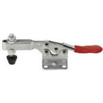
Toggle Clamp
| Product name | Horizontal Handle |
| Model number | MC01-3 |
| Characteristics | Hold Down, Flange Base Type. Low Profile-designed. |
* Orange colored cells in the table below indicate the part numbers that were actually used in this app. example.
Selection criteria
Improves workability with a single lever action
Back to page top
Available sizes
■Toggle Clamps -Horizontal Handle-
| Main body material | EN 1.0038 Equiv. | EN 1.4301 Equiv. |
| Surface treatment | Trivalent chromate | - |
| Clamping force (N) | 264.6 | 264.6 | 400 | 882 | 2352 | 264.6 | 264.6 | 882 | 2352 |
| Weight (g) | 30 | 35 | 60 | 130 | 265 | 30 | 35 | 130 | 265 |
| Arm open / close angle | 90° | 90° | 90° | 85° | 90° | 90° | 90° | 85° | 90° |
| Handle open / close angle | 75° | 75° | 75° | 73° | 65° | 75° | 75° | 73° | 65° |
| Overall width | 23.8 | 23.8 | 23.8 | 36 | 35 | 23.8 | 23.8 | 36 | 35 |
| Overall height (Clampled) | 17.3 | 17.3 | 34.6 | 37.8 | 47.6 | 17.3 | 17.3 | 37.8 | 47.6 |
| Overall height (Unclamped) | 48.3 | 48.3 | 78 | 96.8 | 110.2 | 48.3 | 48.3 | 96.8 | 110.2 |
| Overall length (Clamped) | 71 | 69.1 | 100.6 | 143.5 | 173 | 71 | 69.1 | 143.5 | 173 |
| Clamp position | Fixed | Variable | Variable | Variable | Variable | Fixed | Variable | Variable | Variable |
| Accessory | Nylon Bolt | Bolt with rubber
Material: NBR
Hardness: Shore A70 | Stainless steel bolt |
* Please see the product pages for shape details and dimensions.
Back to page top
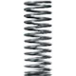
Round Wire Springs
| Product name | Round Wire Coil Springs/Deflection 40%-45%/O.D. Referenced |
| Model number | WL14-65 |
* Orange colored cells in the table below indicate the part numbers that were actually used in this app. example.
Selection criteria
Used to raise the measurement section when the toggle clamp is released.
Back to page top
Available sizes
■Round Wire Springs -Spring Constant 0.5 ~ 1.0N/mm-
Deflection
(Free length ratio) | Material | O.D.
range | Free length
range |
| JIS-SWP-A | EN 1.4301 Equiv. |
| 75% | ○ | ○ | Ø3 ~ 16 | 5 ~ 70 |
| 60% | ○ | ○ | Ø3 ~ 27 | 5 ~ 90 |
| 45% | ○ | ○ | Ø3 ~ 27 | 5 ~ 90 |
| 40% | ○ | ○ | Ø2 ~ 27 | 5 ~ 100 |
| 40% | ○ | ○ | Ø3 ~ 27 | 5 ~ 80 |
| 35% | ○ | ○ | Ø3 ~ 27 | 5 ~ 100 |
| 30% | ○ | ○ | Ø4 ~ 27 | 5 ~ 100 |
| 25% | ○ | ○ | Ø3 ~ 27 | 5 ~ 100 |
■Sizes and Dimensions
| O.D. | Free length | Coil wire DIA. | Solid length | Max. deflection | Load (N) |
| Ø12 | 10 | Ø0.8 | 4.8 | 4 | 4 |
| 15 | Ø0.9 | 7.2 | 6 | 5.9 |
| 20 | Ø0.9 | 7.2 | 8 | 7.8 |
| 25 | Ø0.9 | 7.2 | 10 | 9.8 |
| 30 | Ø1 | 10.5 | 12 | 11.8 |
| 35 | Ø1 | 10.5 | 14 | 13.7 |
| 40 | Ø1 | 10.5 | 16 | 15.7 |
| 45 | Ø1.1 | 15.4 | 18 | 17.7 |
| 50 | Ø1.1 | 15.4 | 20 | 19.6 |
| 55 | Ø1.1 | 15.4 | 22 | 21.6 |
| 60 | Ø1.2 | 22.8 | 24 | 23.5 |
| 65 | Ø1.2 | 22.8 | 26 | 25.5 |
| 70 | Ø1.2 | 22.8 | 28 | 27.5 |
| 80 | Ø1.3 | 34.5 | 32 | 31.4 |
| Ø13 | 10 | Ø0.85 | 5.1 | 4 | 4 |
| 15 | Ø0.9 | 6.3 | 6 | 5.9 |
| 20 | Ø1 | 8.7 | 8 | 7.8 |
| 25 | Ø1 | 8.7 | 10 | 9.8 |
| 30 | Ø1.1 | 13.2 | 12 | 11.8 |
| 35 | Ø1.1 | 13.2 | 14 | 13.7 |
| 40 | Ø1.1 | 13.2 | 16 | 15.7 |
| 45 | Ø1.1 | 13.2 | 18 | 17.7 |
| 50 | Ø1.1 | 13.2 | 20 | 19.6 |
| 55 | Ø1.1 | 13.2 | 22 | 21.6 |
| 60 | Ø1.1 | 13.2 | 24 | 23.5 |
| 65 | Ø1.2 | 18.6 | 26 | 25.5 |
| 70 | Ø1.2 | 18.6 | 28 | 27.5 |
| 80 | Ø1.4 | 37.8 | 32 | 31.4 |
| 90 | Ø1.4 | 37.8 | 36 | 35.3 |
| Ø14 | 15 | Ø1 | 7.5 | 6 | 5.9 |
| 20 | Ø1 | 7.5 | 8 | 7.8 |
| 25 | Ø1 | 7.5 | 10 | 9.8 |
| 30 | Ø1.1 | 11 | 12 | 11.8 |
| 35 | Ø1.1 | 11 | 14 | 13.7 |
| 40 | Ø1.1 | 11 | 16 | 15.7 |
| 45 | Ø1.2 | 15.6 | 18 | 17.7 |
| 50 | Ø1.2 | 15.6 | 20 | 19.6 |
| 55 | Ø1.2 | 15.6 | 22 | 21.6 |
| 60 | Ø1.2 | 15.6 | 24 | 23.5 |
| 65 | Ø1.3 | 22.1 | 26 | 25.5 |
| 70 | Ø1.3 | 22.1 | 28 | 27.5 |
| 80 | Ø1.3 | 22.1 | 32 | 31.4 |
| 90 | Ø1.5 | 43.5 | 36 | 35.3 |
| Ø16 | 15 | Ø1.1 | 8.2 | 6 | 5.9 |
| 20 | Ø1.1 | 8.2 | 8 | 7.8 |
| 25 | Ø1.2 | 10 | 10 | 9.8 |
| 30 | Ø1.2 | 10 | 12 | 11.8 |
| 35 | Ø1.2 | 10 | 14 | 13.7 |
| 40 | Ø1.2 | 10 | 16 | 15.7 |
| 45 | Ø1.4 | 21 | 18 | 17.7 |
| 50 | Ø1.4 | 21 | 20 | 19.6 |
| 55 | Ø1.4 | 21 | 22 | 21.6 |
| 60 | Ø1.4 | 21 | 24 | 23.5 |
| 65 | Ø1.5 | 29.7 | 26 | 25.5 |
| 70 | Ø1.5 | 29.7 | 28 | 27.5 |
| 80 | Ø1.5 | 29.7 | 32 | 31.4 |
| 90 | Ø1.6 | 40 | 36 | 35.3 |
| Ø18 | 20 | Ø1.5 | 10 | 8 | 23.5 |
| 25 | Ø1.6 | 12 | 10 | 29.4 |
| 30 | Ø1.6 | 12 | 12 | 35.3 |
| 35 | Ø1.7 | 16.2 | 14 | 41.2 |
| 40 | Ø1.7 | 16.2 | 16 | 47.1 |
| 45 | Ø1.8 | 19.8 | 18 | 53 |
| 50 | Ø1.8 | 19.8 | 20 | 58.8 |
| 55 | Ø1.8 | 19.8 | 22 | 64.7 |
| 60 | Ø1.8 | 19.8 | 24 | 70.6 |
| 65 | Ø2 | 32 | 26 | 76.5 |
| 70 | Ø2 | 32 | 28 | 82.4 |
| 80 | Ø2 | 32 | 32 | 94.1 |
| 90 | Ø2.2 | 43 | 36 | 105.9 |
| 100 | Ø2.2 | 43 | 40 | 117.7 |
* Other sizes are available. Please see the product pages.
Back to page top
Performance info.
■Spring constant of round wire coil spring, O.D. referenced type (N/mm)
| O.D. | Max deflection (Free length) Type |
| 75% | 60% | 45% | 40% | 40% | 35% | 30% | 25% |
| Ø2 | - | - | - | 0.5 | - | - | - | - |
| Ø3 | 0.1 | 0.3 | 0.5 | 1 | 1.5 | 2 | - | 3.9 |
| Ø4 | 2.9 | 4.9 |
| Ø5 | 2 | 2.9 | 5.9 | 9.8 |
| Ø6 |
| Ø8 |
| Ø10 | 0.2 |
| Ø12 |
| Ø13 | 9.8 | 19.6 |
| Ø14 |
| Ø16 |
| Ø18 | - | 0.5 | 1 | 2.9 | 3.9 | 4.9 | 14.7 | 29.4 |
| Ø20 | - | - |
| Ø22 | - | 29.4 |
| Ø27 | - |
Back to page top
Technical calculations
■Coil spring load calculations
Load = Spring constant x Deflection
Back to page top
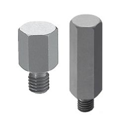
Height Adjust Pin
| Product name | Height Adjust Pins/Hex/B/F Standard |
| Model number | JPRA6-30.00 |
| Characteristics | Can be used for height-adjusting. |
* Orange colored cells in the table below indicate the part numbers that were actually used in this app. example.
Selection criteria
Height accuracy is necessary for this application example.
Back to page top
Available sizes
■Height Adjust Pins- Hex, B/F Standard
| Material | Surface treatment | Hardness |
| EN 1.7220 Equiv. | - | Heat treated hardness 46 ~ 50HRC |
| Black oxide | Heat treated hardness 46 ~ 50HRC |
| Hard chrome plating | Heat treated hardness 46 ~ 50HRC |
| Plating thickness 3µm or more | Plating hardness 750HV ~ |
| EN 1.4301 Equiv. | - | - |
| EN 1.4125 Equiv. | - | Heat treated hardness 50 ~ 55HRC |
■Sizes and Dimensions
Thread DIA.
(Coarse) | Head height | Head
Hex size | Under head
thread length |
| (Configure in 0.01mm increments) |
| M3 | 2.00 ~ 10.00 | 6 | 5 |
| M4 | 7 | 6 |
| M5 | 8 | 8 |
| M6 | 5.00 ~ 30.00 | 10 | 8 |
| M8 | 13 | 10 |
| M10 | 10.00 ~ 50.00 | 17 | 12 |
| M12 | 19 | 15 |
Back to page top
Accuracy Info
■Accuracy of height adjust pins threaded type (Hex)
Head height tolerance: +0.01 / 0
Back to page top
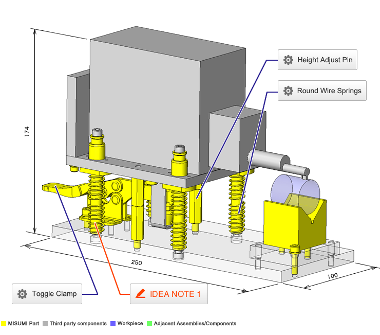
IDEA NOTE Up/down mechanism with springs and bushings + One touch holding.
The inspection instrument movements are guided by bushings and shafts, and raised by the springs. While inspecting, the toggle clamp pushes the inspection instrument down.


