- inCAD Library Home
- > No.000175 Workpiece Gripper Unit with Suction Cups
No.000175 Workpiece Gripper Unit with Suction Cups
21
21
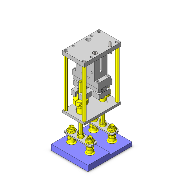
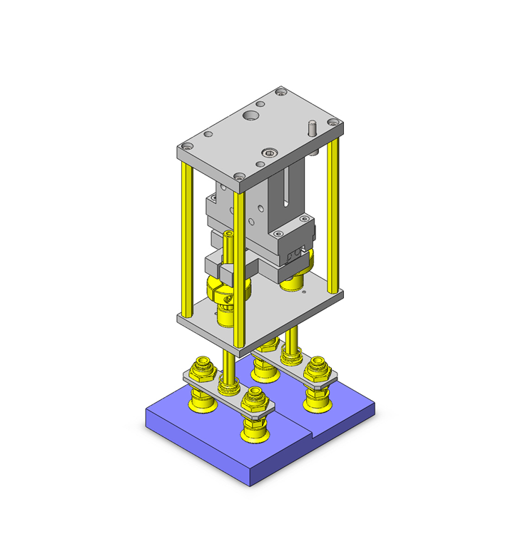
Fixing the sliding suction cup at hands.
Related Category
- * Unit assembly CAD data consists of some sub-assemblies.
Each sub-assembly unit can be used as it is or can be edited.
Application Overview
Purpose
- Purpose
- With the suction cup, various types of plastic cases with different step part heights are transported without change of setups.
- Operation
- When workpiece types are changed, no change over of suction cup types is conducted. Transportation is performed corresponding to plastic cases with different step part heights for different types of products.
The suction cup slides up and down by the spline shaft to absorb workpiece step difference. By fixing the upper part of the spline shaft with an air chuck, horizontal transportation of the suction cup and workpiece is conducted.
- When workpiece types are changed, no change over of suction cup types is conducted. Transportation is performed corresponding to plastic cases with different step part heights for different types of products.
Points for use
- By chucking the slide of the suction cup, transportation of irregular shaped workpieces maintaining their horizontal posture is possible.
Target workpiece
- Shape: Plastic cases with height differences.
- Size: W120 x D100 x H15 (allowable difference in step difference 10mm) mm
- Weight: 800g
Design Specifications
Operating Conditions or Design Requirements
- Suction cup stroke 15mm
- Suction cup maximum reaction force: 7.93N x 2 (including weights of the guide, etc.)
- Hand gripping force: About 70N (air pressure 0.4MPa)
70 x 70% = 49N - External size: W100 x D60 x H230mm
Required Performance
- Allowable transportable load: 8N
Selection Criteria for Main Components
- Gripping force of the air chuck: 46.2N or more
Select an air chuck with a gripping force of 49N.
Design Evaluation
Verification of main components
- Verify the allowable transportable load by air chuck gripping for feasibility of transporting workpieces.
- Check the allowable transportable weight by air chuck gripping
- Conditional values: workpiece weight: M1 = 800g = 0.8kg, weight of a structure gripped by the air chuck: M2 = 0.4kg, gravitational acceleration g = 9.8m/s², friction coefficient µ = 0.5 (rubber vs. metal), spring constant of the spring: k = 0.2N/mm, maximum deflection of the spring: L = 21.5mm, gripping force of the air chuck: H = 49N
- Maximum downward load by the springs (2 pieces) : S = k x L x 2 = 0.2 x 21.5 x 2 = 8.6N
- Downward load by the structure and springs: W = M2 x g + S = 0.4 x 9.8 + 8.6 = 3.9 + 8.6 = 12.5N
- Maximum transportable weight with the chuck: P = H x µ = 49 x 0.5 = 24.5N
Allowable transportable weight: Q = P - W = 24.5 - 12.5 = 12.0N - Downward load of the workpiece: N = M1 x g = 0.8 x 9.8 = 7.8N This corresponds to 65% ( = 7.8 / 12 x 100) of the allowable transportable weight, and thus, the workpiece can be transported.
- Checking the allowable transportable weight of the suction cup
- Conditional values: Pad size = Ø20mm ∴ pressure receiving area S = 3.14cm², vacuum
Sling up capacity: W [N] = P x S x 0.1 / t = 80 x (3.14 x 4pieces) x 0.1 / 4 = 25.1N
⇒Allowable transportable weight of the air chuck 24.5N ≤ allowable transportable weight of the suction cup 25.1N Thus, the workpiece transporting force is satisfied.
- Conditional values: Pad size = Ø20mm ∴ pressure receiving area S = 3.14cm², vacuum
Other Design Consideration
- Irregular-shaped workpieces are sucked by sliding the suction cup with the guide.
Status of irregular-shaped workpieces can be retained by holding and fixing the slide with the chuck. - Rubber sheets are affixed on the inner sides of the chuck craw to retain the position of the slid spline shaft.
Explore Similar Application Examples
Page
-
/
-


